Mor Temor
Arch. Mor Temor is international Architecture firm committed to designing unique buildings and one of a kind architectural concepts.

2.24 Floating Offshore structures
Since the development of the North Sea oil fields, the Norwegians have been leaders in the field of offshore structures leading to technology that has been applied to innovative floating structures (Watanabe, 2003).
The offshore system is divided into two parts. The first part presents structures which floated during construction and tow-out but were finally placed on the sea bed or on a firm structure, while the second part is devoted to permanently floating concrete structures.
Fig. 50 shows four examples of these structures. One of them, the gravity platform (which temporarily floated during construction), penetrates the sea floor; at present, fixed structures have been built for water depths up to about 300 m. Two of the structures, the semi-submersible and the floating production ship, are free-floating; both the ship and the semi-submersible are kept in position by a spread mooring system (Faltinsen, 1995).
Lastly, the tension leg platforms (TLP). These tension platforms are kept in position by a tension leg system; are restrained from oscillating vertically by tethers, which are vertical anchor lines that are tensioned by the platform buoyancy being larger than the platform weight. Current examples of tension leg platforms (TLP) operate in depths of exceeding1300 meters. This system provides the most cost effective solution for mooring in deep water. Fig. 51 illustrates typical TLP applications (Strait, 2001).
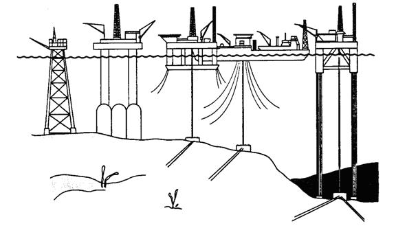
Fig. 50 Four types of offshore structures. From left to right we have, gravity platform, semi-submersible, floating production ship, tension leg platforms (TLP).
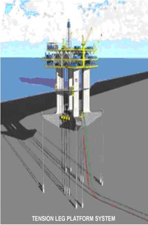
Fig. 51 Tension leg platform system.
Temporarily Floating Structures
In the mid-sixties, large oil deposits were discovered in the North Sea, mainly in the British and Norwegian sectors. The oil companies showed enormous interest in these fields, in spite of the fact that the exploitation techniques that would be required were comparatively unknown, since previously oil had been extracted only on land and inshore in shallow water, but not in water150 m and more deep. Furthermore, some of the most promising oil fields are situated quite far north, some 150 to 250 kilometers offshore and exposed to storm waves of up to 30 m and gale force winds of 240 to 260 km/h.
Such geographic and climatic conditions demand that site installation work be kept to a minimum and storage capacity be created, since production must continue even when tankers cannot load and where there is no pipeline to the shore. These requirements led to the development of completely new production platforms.
Concrete gravity structures with steel decks appeared to be very well suited to these conditions. Designs for different types of platforms were rapidly prepared and submitted to the interested oil companies.
Most designs are similar in overall size and have basically the same concept (see Fig. 52). They comprise a cellular concrete caisson, acting as foundation and providing oil storage capacity, but also providing buoyancy during construction and tow-out. The foundations support one or more concrete towers, with a steel deck carrying the process plant and equipment spanning between them. The cells and towers are of reinforced and post-tensioned concrete, while the deck is a steel structure.
The platform is used as a drilling platform, with derricks, storage for mud, cement and pipes, power generation and living quarters, and as a production unit providing cooling and separation facilities and storage for the crude oil, together with generators, pumps and reinjection equipment, living quarters, rescue and fire-fighting plant, communications, gas flare off and so on.
The latest platform, now under construction, is of extraordinary size; its total height will be approx.380 m.
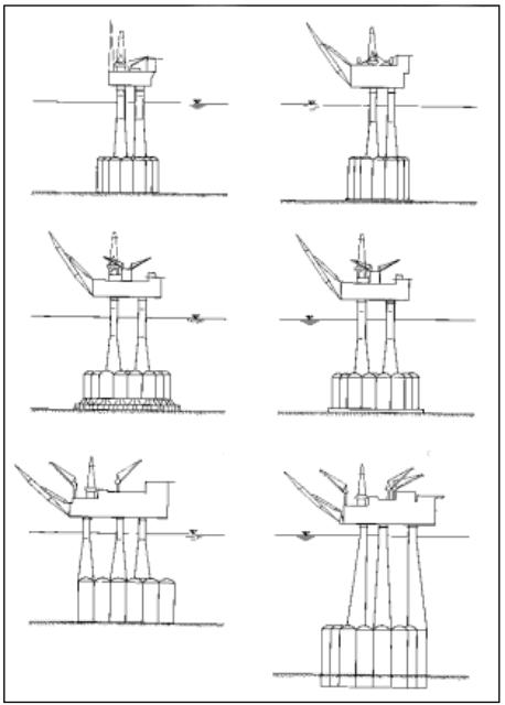
Figure 52: Sections of various gravity platform.
Construction procedure
All these platforms have been or are being built by Norwegian Contractors (NC), who have a construction yard in Stavangeron the west coast of Norway. This is a most favourable region for offshore construction, which demands deep, sheltered water close inshore near to a site. The Norwegian fjords perfectly fulfil these requirements.
The site at Stavanger offers all the facilities required. The construction yard comprises two dry docks, which were created by driving sheet piles into the sea bed, dewatering and excavating the rock to a certain depth. In this way two sites with a total area of about 75,000 mq were obtained.
The general construction procedure for this structure is as follows (Fig. 53);
First the steel or concrete skirts are placed or constructed in the construction yard. Then the foundation slab, lower domes and cell walls are built (Fig. 54). The walls are Slipformed at a rate of 1.5 to 2.0 m per day (Slipforming is a largely mechanized construction procedure, the forms are raised by hydraulic jacks. Slipforming include the short construction time resulting from continuous working with concrete without stopping, monolithic construction without construction joints).
As soon as the structure has reached a stage where it will float, if necessary with the help of an air cushion inside the skirts, construction of the cell walls is interrupted. The dry dock is then flooded and the piling removed.
The structure is now brought into deeper water and there construction of the walls is continued (Fig. 55). After the cells have been closed by their upper domes, slipforming of the tower shafts is started (Fig. 56). Slipforming is exacting work, as diameter and wall thickness vary and reinforcement, post-tensioning cables and concrete must be placed in simultaneous working. When the concrete structure is complete, it is towed out to deeper but still sheltered water (Fig. 57), the dry towers is then flooded, where deck mating is carried out (Fig. 58) (VSL,1992).
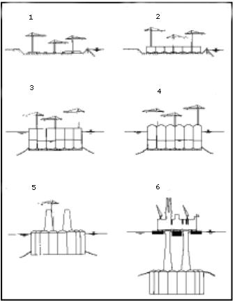
Figure 53: Typical construction procedure for a gravity platform.
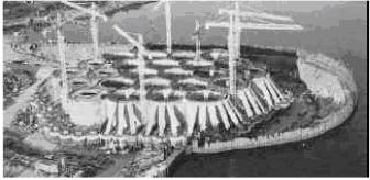
Figure 54: Gravity platform under construction in the dry dock.
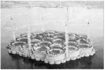
Figure 55: Gravity platform during construction of cell walls.
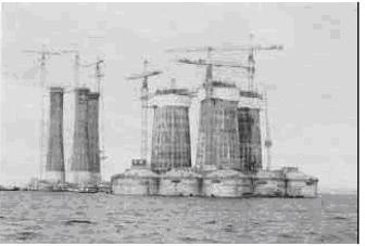
Figure 56: Con deep platforms during construction of tower shafts.
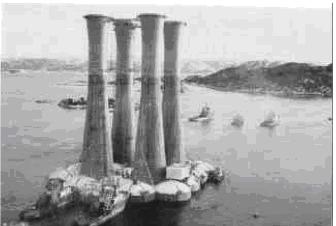
Figure 57: Tow-out of the concrete strucuture of a Gravity platform.
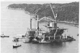
Figure 58: Deck mating, i.e. of deck structure onto the concrete structure.
Arch. Mor Temor