Mor Temor
Arch. Mor Temor is international Architecture firm committed to designing unique buildings and one of a kind architectural concepts.

2.15 James M. Powers Floating Bridge
James M. Powers have invented in 2007 new and useful improvements in Cable stayed pontoon bridges. The objects and advantages of the invention, and others as well, are realized by a floating bridge and by a method of constructing a bridge over a wide waterway without having to build massive piers on the bottom of the waterway to support the bridge towers. Another object is to realize the economic advantages of repetitive remote fabrication probably in a modern shipyard of an essentially complete bridge; roadway truss, tower, pontoon and unique support legs.
In a broad form of the invention, marine vessels designed to be linked short term, or for long periods, span a waterway and function as a motor vehicle bridge. In a preferred embodiment; a cable stay bridge formed by one or more bridge modules extends across a waterway. Each bridge module includes a pontoon, a tower assembly, and a bridge deck assembly. Each tower supports a bridge deck/roadway centered at the tower, extending in opposite directions, supported by means of cable stays supported high on the tower and arrayed along the bridge deck/road/way. Each tower is supported in turn by a long pontoon floating below the base of the tower and extending in opposite directions from the tower but oriented transversely with the direction of the bridge deck/roadway. The tower consists of an assembly made up of a vertical mast attached to the pontoon and a cable stay support member designed to move up and down on the mast. The mast is supported by bipod legs, or brace members, anchored at the apex of the tower with their bases spread equidistant from the base of the tower on the pontoon. The pontoon is made long enough to prevent the tower from leaning due to wind on either side of the bridge. The pontoon is tethered at its center pivotal as below the mast base from the bottom of the pontoon extending to the bottom of the waterway. The pontoon is also tethered from pontoon bottom to pontoon bottom at each pivotal axis by supplementary tethers between pontoons that supply a means to stabilize the spacing between the pontoons. The pontoon is also adjustably tethered from pontoon bottom at bow and stern by supplementary tethers between pontoons that supply a means to adjustably pivotally orient the pontoons to parallel variable water currents.
These and other object and advantages of the present invention will be fully apparent from the following description when taken in connection with the annexed drawings, in which:
Fig. 31 is a perspective view of a floating bridge constructed according to the invention, with bridge modules erected and tethered to bottom of a body of water;
Fig. 32 is a perspective view showing bridge modules linked to create a bridged crossing with pontoons oriented parallel to varying currents and showing a pair of towing apparatuses.
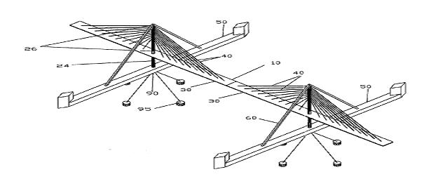
Fig. 31 Perspective view of a floating bridge constructed according to the invention, with bridge modules erected and tethered to bottom of a body of water.
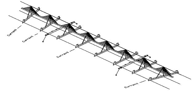
Fig. 32 Perspective view showing bridge modules linked to create a bridged crossing with pontoons oriented parallel to varying currents and showing a pair of towing apparatuses.
Arch. Mor Temor